The
ultimate
structural engineering course for beginners
Gain hands-on expertise from recently delivered projects and download top structural design software for free directly from this website. Then, master these powerful tools and industry-leading techniques with the full training course offered right from this homepage.


Master Structural Design: From Basics to Global Projects
Welcome to Structural-Engineer.Odoo.com – your go-to hub for practical, hands-on structural design training.
Whether you're a student, graduate, or seasoned professional, learn to confidently design real buildings, from fundamental hand calculations to advanced modeling. Our training covers industry-leading software like ProtaStructure 2025, Tekla, ETABS, SAP2000, and more. Plus, get access to free downloads for top structural analysis software to kickstart your learning journey.
Gain the software-driven, code-compliant skills that top firms demand and take your structural engineering career to the next level.
Turn Practice into Structural Design Expertise
Want to become a structural design expert? Our full course helps you sharpen your skills by letting you work with dozens of real architectural plans. Each plan comes with its complete structural design solution, showing you exactly how it was built.
These practical, hands-on projects are your key to mastering the code-based, software-driven design skills that leading engineering firms are looking for. The more you practice, the more proficient and capable you'll become, getting you ready to confidently take on real-world projects.
Ready to put your skills to the test?
Residential
Project 1
Commercial
Project 2
A quick overview of what to expect..
Structural Engineering
Our full training course helps you move beyond classroom theory into real-world structural engineering. You'll work with actual architectural plans from recently completed commercial and residential projects (starting with those labeled as Projects 1 and 2 above). Step by step, you'll learn how to approach and carry out the structural design of each project—just like it’s done in practice.
Free Software and Tools
As part of the full training course on this website, you'll get free access to ProtaStructure 2025, the latest and leading structural engineering software in the industry. It's a powerful 3-in-1 package for modeling, structural analysis, and detailing. (see the software download button near end of this homepage).
But that's not all! We'll also provide free copies of the design codes used throughout this website, along with a curated collection of additional tools that structural engineers use to make their work easier and more efficient.
And there's more good news: we'll be providing additional software downloads including ETABS, Tekla, SAP2000, Midas Civil, and others! So stay tuned until the end to unlock all these valuable resources. The full training course begins right from this homepage (below) and extends over several pages (click the next page button at the bottom of this page to continue with the coursework).
If you're short on time right now, just hit one of the share buttons below to save this website—email it to yourself or share it with a friend. That way, you can easily come back and give it your full attention when you're ready.

Full Structural Design Training Course (ProtaStructure 2025)
Let's dive right in!
What is Structural Engineering?
Structural engineering is a branch of civil engineering that focuses on the design, analysis, and construction of structures that can safely support loads and resist external forces. It ensures that buildings, bridges, towers, and other structures remain stable and secure throughout their service life.
What Do Structural Engineers Do?
Structural engineers play a critical role in the construction process. Their job is to design the "skeleton" of a structure—the framework that holds everything up. They calculate loads, select appropriate materials, and design the structural systems (like beams, columns, slabs, and foundations) to ensure the building can safely support its weight and any external forces like wind, snow, and earthquakes.
Beyond the design, structural engineers also prepare detailed reports and drawings that must be submitted to government authorities—such as municipal or city offices—for project approvals. These documents typically include structural calculations, load analysis, foundation design, and compliance with local building codes. This tutorial will show you exactly what such reports look like and how they are prepared in practice.
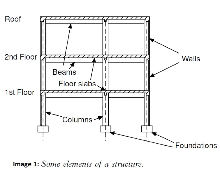
Understanding Structural Members
A building is made up of several key structural components:
- Slabs – Horizontal flat elements that form the floors and ceilings.
- Beams – Horizontal supports that carry loads from the slabs to the columns.
- Columns – Vertical supports that transfer loads from beams down to the foundation.
- Walls – Can be either structural (load-bearing) or non-structural (partition walls).
- Footings (Pad Foundations) – Thick concrete blocks at the base of columns that distribute loads safely into the ground.
- Roof – Protects the interior and also acts as a structural element depending on the design.
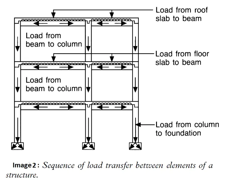
How Loads Are Transferred
All structural members work together to transfer loads safely from the top of the building to the ground. Here’s how it works:
- Live loads (from occupants, furniture, and use) and dead loads (weight of the building itself) act on the slabs.
- The slabs transfer those loads to beams.
- Beams then carry the loads to columns.
- Columns transmit the loads down to the footings, which spread the force into the soil below.
- At the same time, wind loads act on exterior walls, and snow loads (in applicable regions) press down on the roof—both of which must also be accounted for in the design.
Together, these elements form a load path:
Load → Slab → Beam → Column → Foundation → Ground
Please note:
- In some buildings, we use flat slabs (explained later in the tutorial), which transfer loads directly to the columns without beams.
Load Path:
-
For traditional slabs:
Slab → Beam → Column → Foundation → Ground -
For flat slab systems (no beams):
Flat Slab → Column → Foundation → Ground
-
For traditional slabs:
- Both systems aim to safely transfer all loads from the top of the building down to the soil, but the structural behavior and design approach differ slightly.
Understanding Limit States in Structural Design
When designing any building, structural engineers aim to ensure the structure remains safe and functional throughout its entire design life. To do this, we use a concept called Limit State Design, which involves checking the structure under two main conditions:
1. Ultimate Limit States (ULS)
These are conditions that can lead to structural failure or collapse, such as:
- Excessive bending
- Shear failure
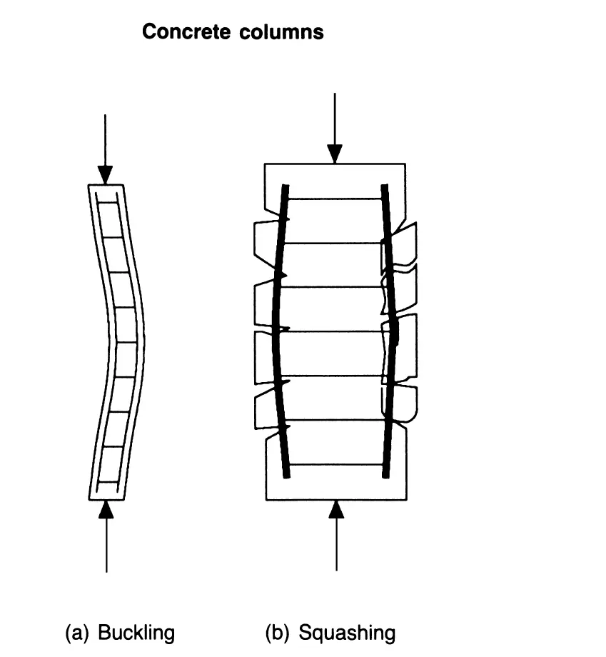
- Buckling or crushing of columns
Designing for ULS ensures the structure has enough strength and stability to carry all expected loads safely.
2. Serviceability Limit States (SLS)
These affect the usability, comfort, or appearance of a building without causing collapse. They include:
- Excessive deflection
- Cracking in concrete
- Vibrations
Designing for SLS ensures the building remains comfortable and durable for occupants over time.
Example:
- For beams: ULS (bending and shear) is usually critical.
- For slabs: SLS (deflection) often governs the design.
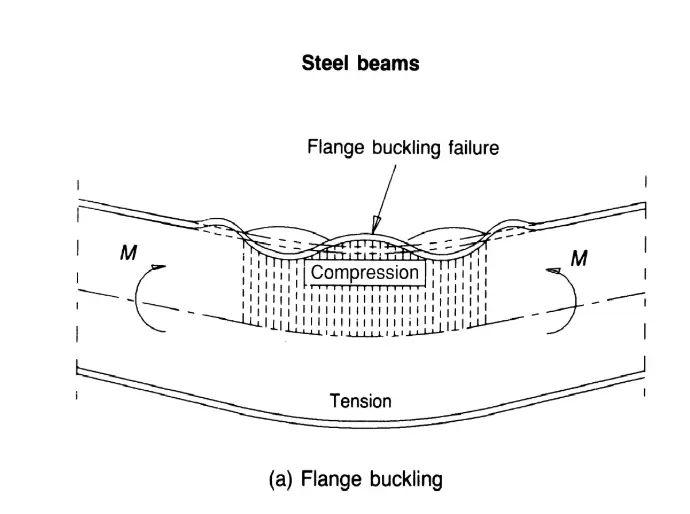
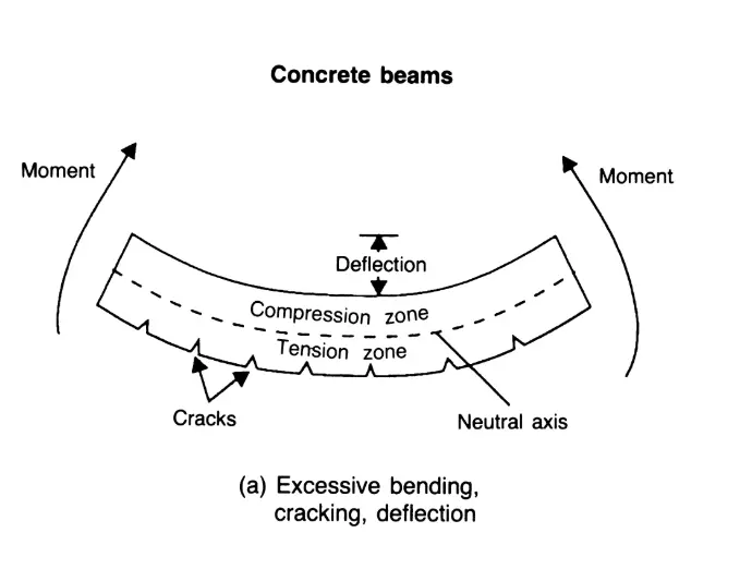
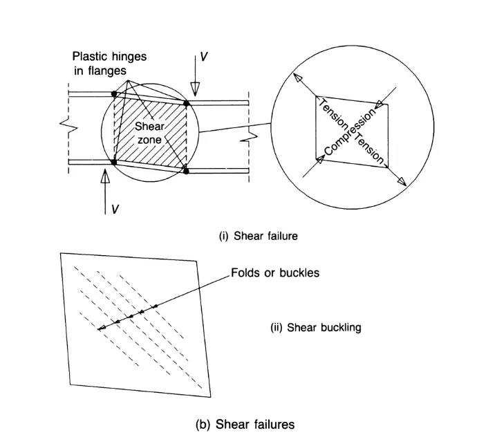
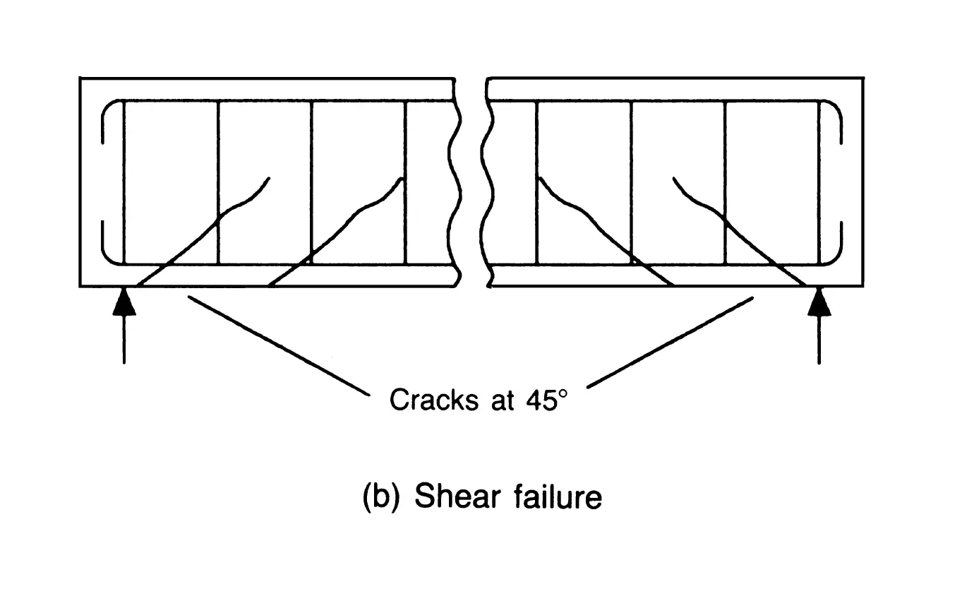
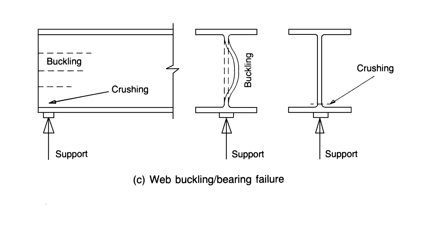
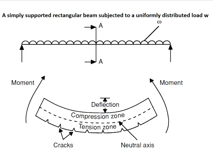
Swipe left on the image below to view different types of structural failure.
Reports for Project Approval
In real-world practice, structural engineers prepare reports showing that all limit states have been checked and satisfied. These reports are submitted to the municipal or city authorities as part of the project approval process. This full training course will guide you through how such reports are prepared and what they include.
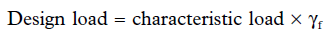
Characteristic & Design Values
In practice, engineers must design for uncertainties in both:
- Material strength (may be weaker than expected)
- Loads (may be heavier than expected)
So we use:
-
Characteristic Values
- Material strength: taken as the value exceeded by 95% of test results
- Load: taken as a conservative estimate from codes
-
Design Values
- Adjusted using Partial Safety Factors to ensure extra safety
The design strength is obtained by dividing the characteristic strength by the partial safety factor for strength, γm  :
:
Design Strength = Characteristic Strength ÷ γm
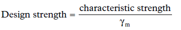
The design load is obtained by multiplying the characteristic load by the partial safety factor for load, γf  :
:
Design Load = Characteristic Load × γf
Design is safe if:
Design Strength ≥ Design Load
Types of Loads on Structures
1. Dead Loads (Gk)
These are permanent loads, including:
- Self-weight of structural elements
- Finishes
- Fixed equipment
2. Imposed Loads (Qk)
Also called live loads, including:
- People
- Furniture
- Snow on the roof
These are more variable and depend on building use (residential, office, hospital, etc.)
3. Wind Loads (Wk)
Can apply pressure or suction on walls and roofs. Must be carefully considered, especially for:
- High-rise buildings
- Lightweight roofs
- Masonry walls
Load Combinations
To make sure the building can handle real-world conditions, we combine different loads (e.g. dead + live + wind) and apply appropriate safety factors. The combination that causes the worst-case scenario (maximum bending, shear, or deflection) is used for final design checks.
Design Codes
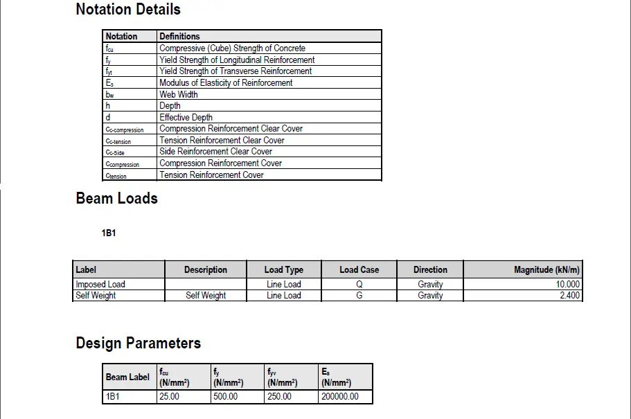
Design codes are official guidelines used by engineers to ensure buildings are safe, durable, and compliant with legal standards. They provide rules for calculating loads, sizing structural members, and checking performance under different conditions. Some of the most widely used structural design codes around the world include the Eurocodes (EN), British Standards (BS), American codes like ACI (concrete) and AISC (steel), and Indian Standard Codes (IS). In this course, we will initially be using British Standards (BS) that are specifically relevant to building construction—such as BS 8110 for the design of reinforced concrete structures, BS 5950 for structural use of steel, BS 648 for the unit weights of building materials used in calculating dead loads and BS 6399 (now partly replaced by Eurocodes) for determining imposed (live) loads and wind loads.
These codes will guide our calculations and help ensure the designs meet safety and performance standards.
As part of this full training course, you can download for free the relevant BS codes mentioned above using the link provided below. These documents will be essential references throughout your learning journey.
Latest Eurocode: BS EN 1992-1-1:2023
We're excited to announce that BS EN 1992-1-1:2023, the very latest Eurocode, is now available! You can get a preview right here, and then download your copy using the button above.


Let's Design!
We’ll begin our journey by designing individual structural elements—starting with simple models of beams, slabs, columns and footings. These basic examples will help you grasp the core design principles without being overwhelmed. After mastering the fundamentals, we’ll move on to designing full structural systems based on real architectural plans from actual projects. This step-by-step approach ensures a smooth transition from theory to practical, real-world structural engineering.
Understanding Beams
Beams are horizontal structural elements that support loads from slabs, walls, or other elements above them. They transfer these loads mainly through bending and carry them to the columns or supporting walls at their ends. When loaded, beams experience tension at the bottom and compression at the top—this behavior is key to their design. In the British Standards (BS 8110), beam design involves checking for bending moment, shear force, and deflection to ensure the beam is strong enough and won’t fail or deform excessively. Proper reinforcement is then provided to resist these forces and ensure safe performance throughout the building’s lifespan.
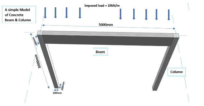
Example 1
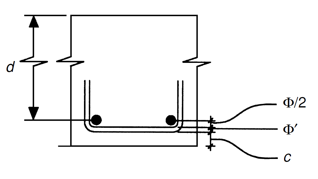
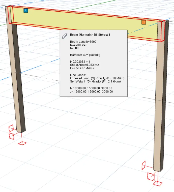
Consider the simple model shown below:
A reinforced concrete beam with a span of 5 meters and a rectangular cross-section measuring 0.2 m in width and 0.5 m in depth is simply supported between two concrete columns, each 3 meters tall with a square cross-section of 0.2 m × 0.2 m. The beam is subjected to a uniformly distributed imposed load of 10 kN/m. Assume the characteristic strength of steel reinforcement, f_y is 500N/mm² and the characteristic compressive strength of concrete, f_cu is 25N/mm².
Design the required reinforcement for the beam.
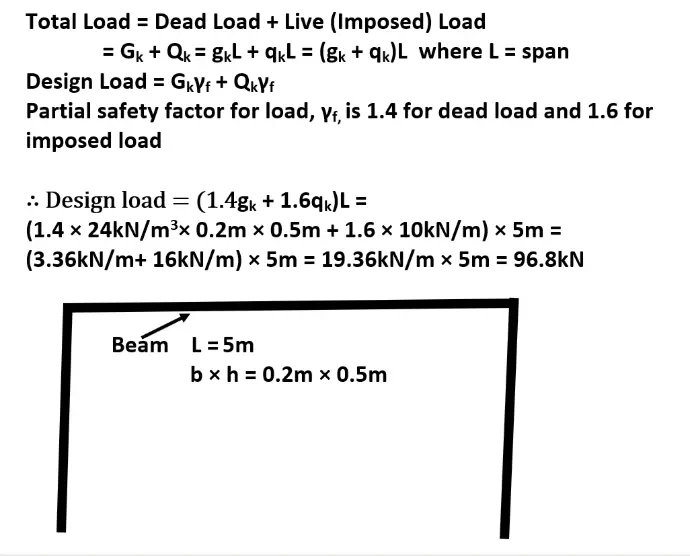
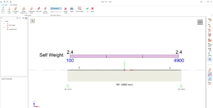
From the BS Codes you have downloaded above, refer to BS 8110-1 and locate table 2.1 (page 9) to obtain the partial safety factors, γf, for dead load and imposed load as 1.4 and 1.6 respectively. Then refer to BS 648 Schedule of Weights of Building Materials (page 25) to find the unit weight of reinforced concrete, given as 24 kN/m³. With this information, we can now find the design load as follows:
Design Load, w = 1.4 × beam self-weight (dead load) + 1.6 × imposed (live) load
w = 1.4 × 0.2m × 0.5m × 24kN/m³ + 1.6 x 10kN/m
w = 3.36kN/m + 16.0kN/m
w = 19.36kN/m
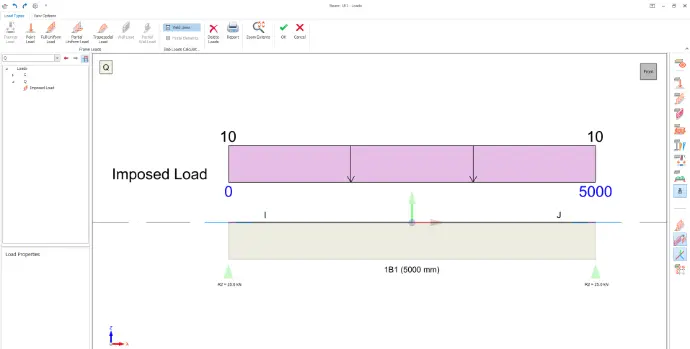
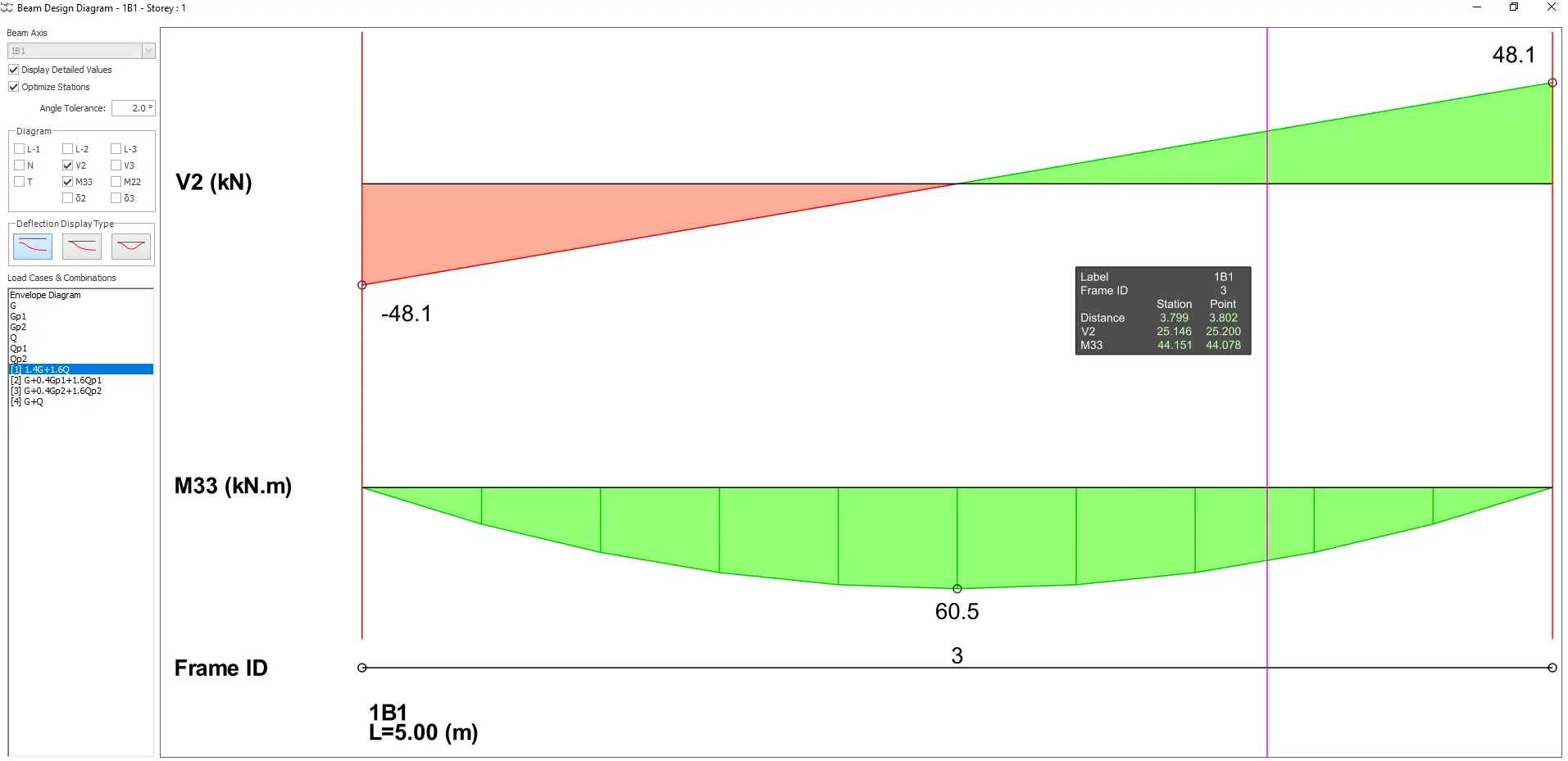
For a simply supported beam under UDL (uniformly distributed load), the bending moment is maximum at mid-span while shear is maximum at the supports (refer to design tools below). Let's now compute the maximum design moment and shear.
Maximum Design Moment, M = wL² / 8
M = 19.36kN/m × (5m)² / 8
M = 60.5kNm
Maximum Design Shear, V = wL / 2
V = 19.36kN/m × 5m / 2
V = 48.4kN
- Bending
Next, we compute the required areas of reinforcement.
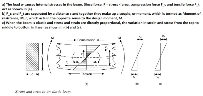
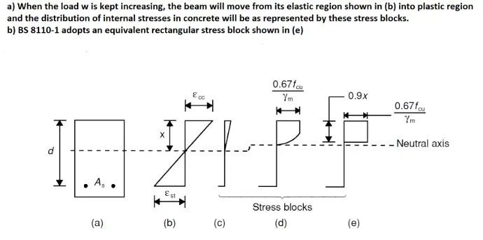
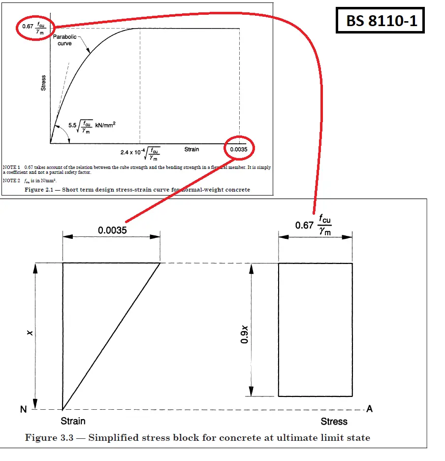
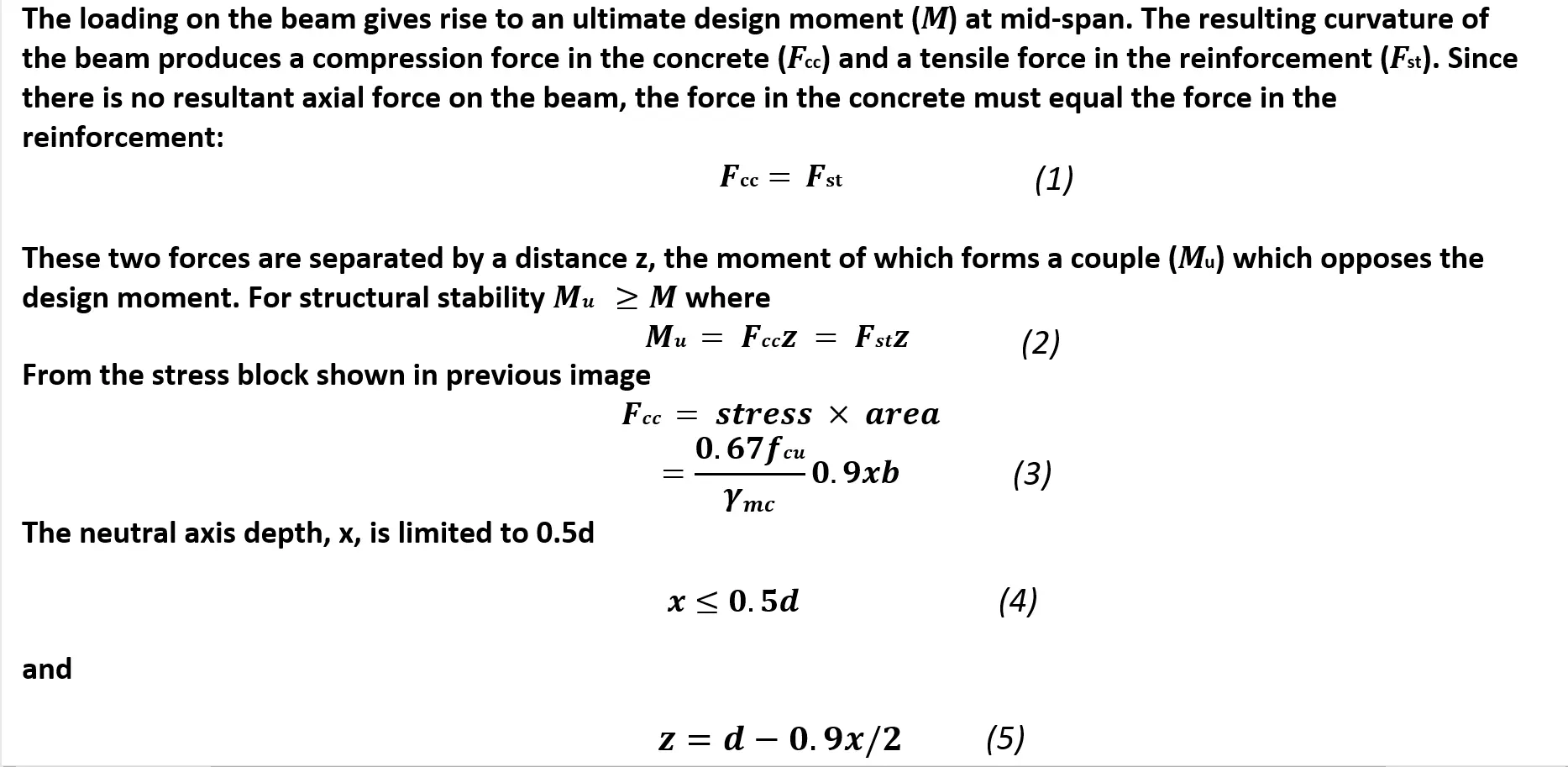
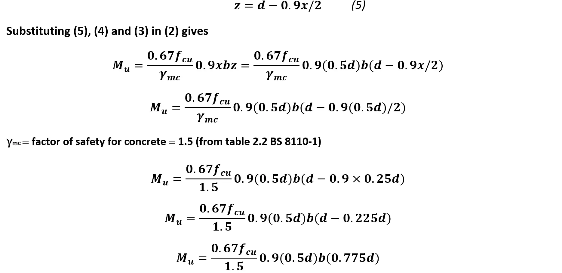
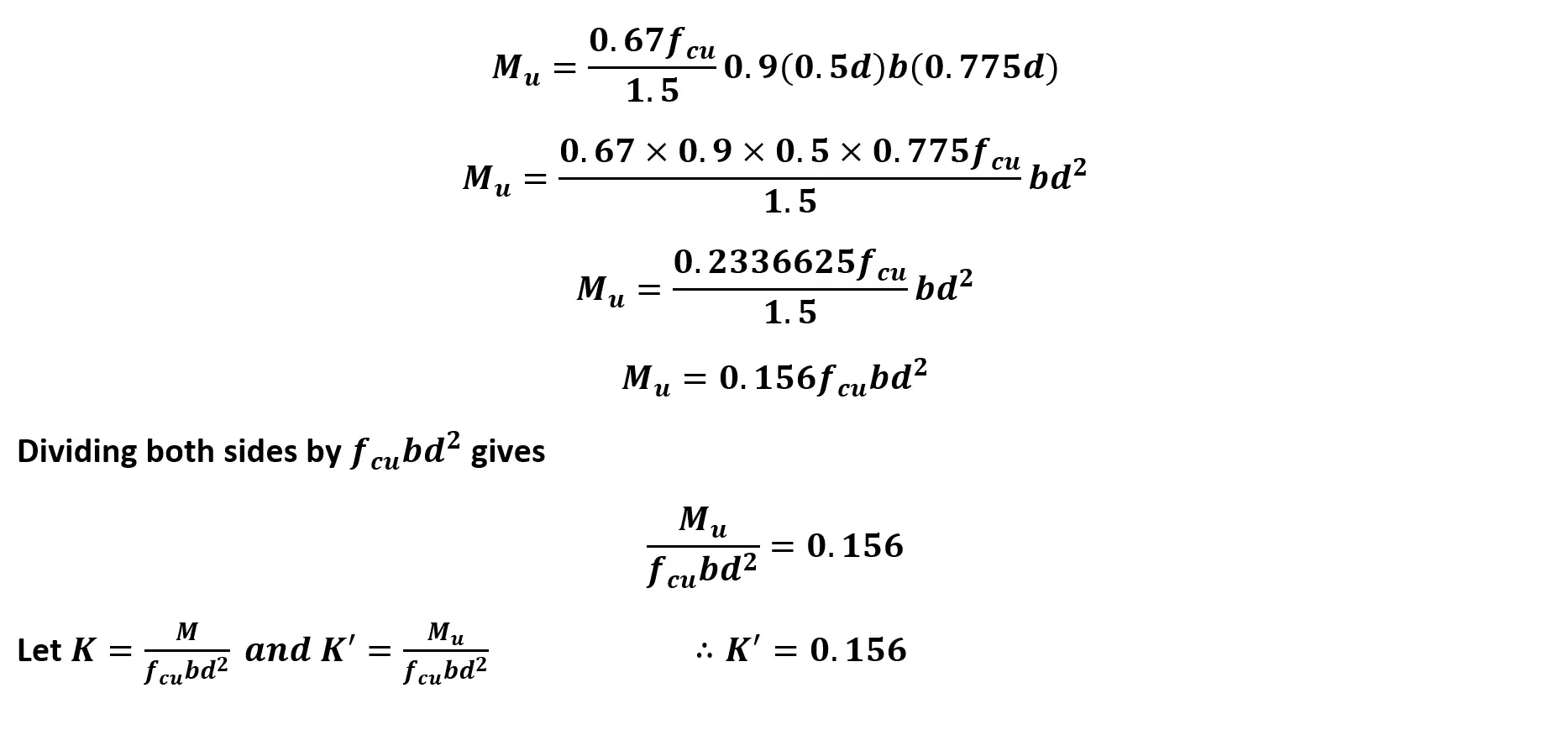
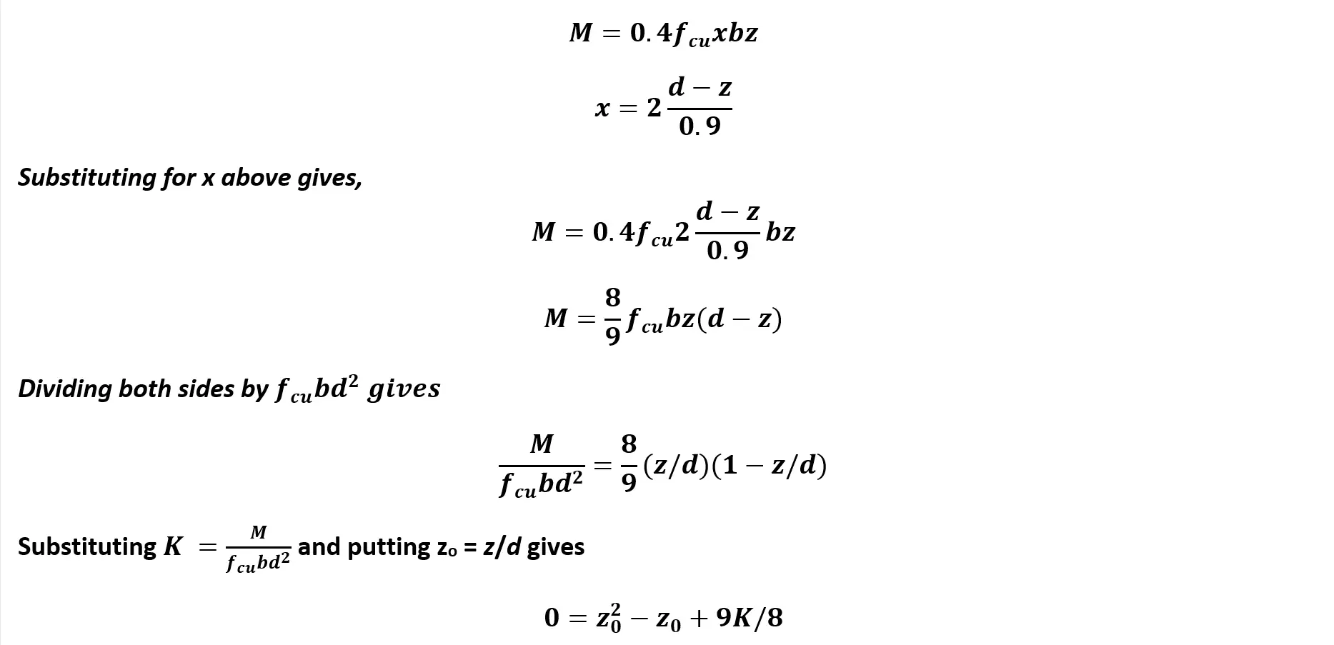
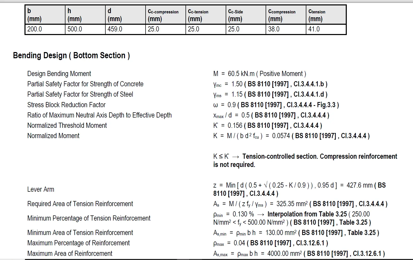
Refer to BS 8110-1 clause 3.4.4.4. Design formulae for rectangular beams (page 26). Notice that K'=0.156 and K=M/bd²f_cu. If you're interested in their derivation, swipe left on the image below.
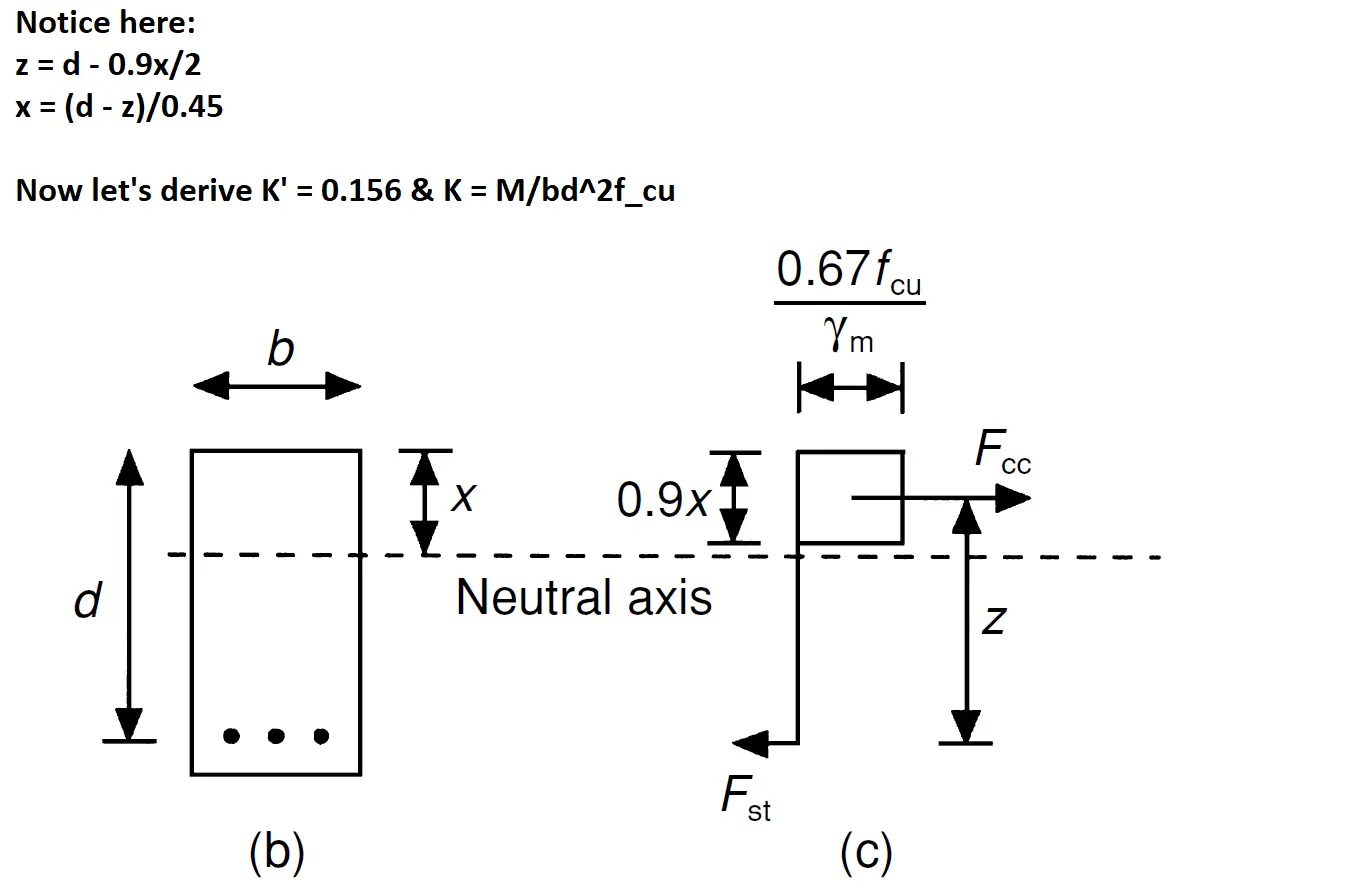

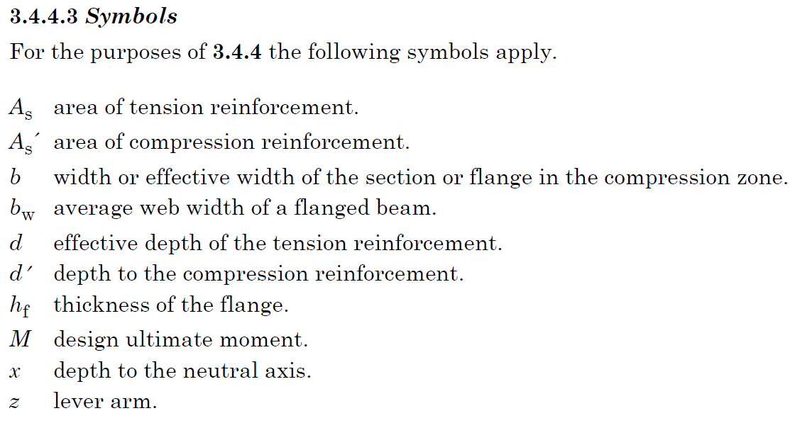
Let's calculate the beam's effective depth, d, given its overall depth, h = 500mm.
Assume diameter of main bars, φ=16mm, diameter of links, φ'=8mm and concrete cover, c=25mm.
d = h - c - φ' - φ/2
d = 500 - 25 -8 - 16/2
d = 459 mm
Let's check the beam's ultimate moment capacity, M_u = 0.156f_cubd²
M_u = 0.156 × 25 × 200 × 459²
M_u = 164.33 kNm
Check, design moment, M < M_u; 60.5 kNm < 164.33 kNm
Hence, the beam is satisfactory, and no compression reinforcement is required (singly reinforced section sufficient).
Let's calculate required tension reinforcement
K = M/bd²f_cu
K = (60.5 × 10^6) / (25 × 200 × 459²)
K = 0.05743
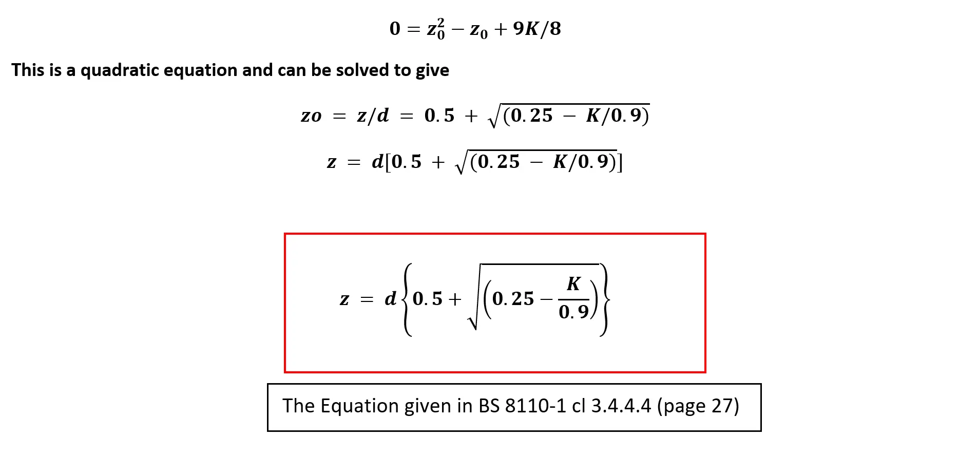
z = d (0.5 + √(0.25 - K/0.9) )
z = 459 (0.5 + √(0.25 - 0.05743/0.9) )
z = 427.56 mm
Check: z ≤ 0.95d = 0.95 × 459 = 436.05mm. Hence use z = 427.56 mm as it is the lesser.
Area of steel, A_s = M/0.87f_yz
A_s = (60.5 × 10^6) / (0.87 × 500 × 427.55)
A_s = 325.3 mm²
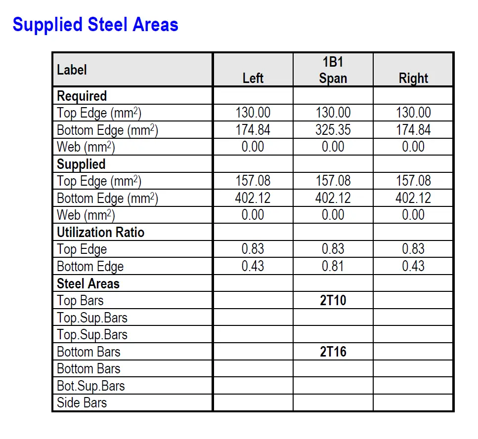
Reinforcement: Convert this area into bar sizes and number of bars.
Rather than waste valuable time computing this manually (A_s / n (π φ² / 4) ), we have design tools for you that make such computations much easier to perform, save you time and drastically reduce chances for error. Download them now for free.
Download Design Tools (FREE)
From the tool you have downloaded above, the eligible steel reinforcement bar configurations are 3T12 (339mm² ), 2T16 (402 mm²), 2T20 (628mm² ). Let's select 2T16 bars.
Reinforcement: Provide 2 T16 bars (A_s = 2 × 201 = 402 mm² ).
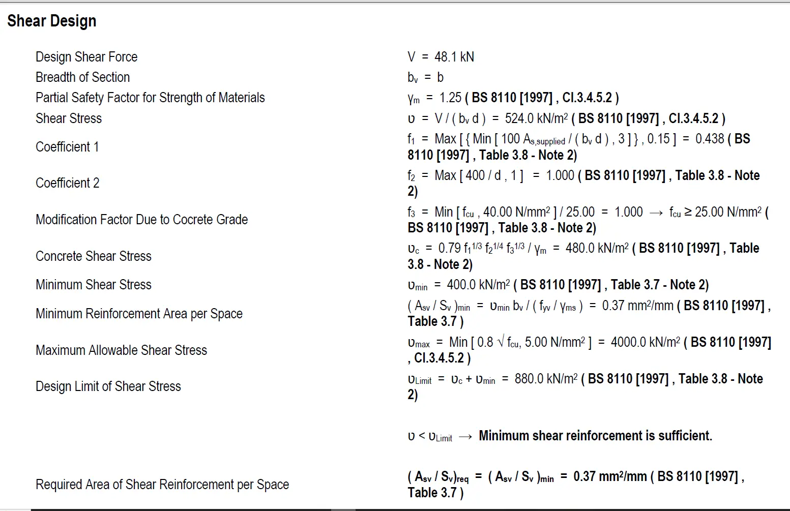
2. Shear
Let's now perform Shear Design. Refer to BS 8110-1 cl 3.4.5 (page 28).
Design shear stress, v = V / (b d)
v = 48.4 × 10³ / (200 × 459)
v = 0.527 N/mm²
Check if v ≤ 0.8√f_cu or 5 N/mm² whichever is the lesser (BS 8110-1 requirement)
v = 0.527 N/mm² ≤ 0.8√25 N/mm² or 5 N/mm²
v = 0.527 N/mm² ≤ 0.8 × 5 N/mm² or 5 N/mm²
v = 0.527 N/mm² ≤ 4 N/mm² or 5 N/mm² hence OK
Let's find the design concrete shear stress, v_c. Refer to BS 8110-1 table 3.8 (page 30). Simply plug in the values into the formula provided under the table.
v_c = 0.48 N/mm²
According to BS 8110-1 table 3.7 (page 29), our design shear stress, v, falls within 0.5v_c < v < (v_c + 0.4)
= 0.5 × 0.48 < 0.527 < (0.48 + 0.4)
= 0.24 < 0.527 < 0.88 N/mm²
and therefore nominal links are required according to
A_sv / s_v ≥ 0.4b / 0.87f_y
A_sv / s_v ≥ (0.4 × 200) / (0.87 × 500)
A_sv / s_v ≥ 0.1839
BS 8110-1 clause 3.4.5.5 further specifies the link spacing, s_v ≤ 0.75d = 0.75 × 459 = 344mm
To convert the ratio of area of links to link spacing (A_sv / s_v), we have a tool for you. It's bundled together with the first tool mentioned above. Click on the download button above to get this second tool if you have not yet done so. It's free.
From the tool you have just downloaded, find A_sv / s_v ≥ 0.1839 to select appropriate link diameter and spacing. Select 0.335 (8mm diameter links at 300mm spacing).
Provide H8 links at 300mm centres.
3. Deflection
Let's perform deflection check. Refer to BS 8110-1 cl 3.4.6 (page 32 of the BS codes you have downloaded from the button above).
Actual span/effective depth ratio = 5000mm/459mm = 10.9
Allowable span/effective depth ratio = Basic span/effective depth ratio × Modification factor
Basic span/effective depth ratio = 20 (refer to BS 8110-1 table 3.9, page 33)
To obtain the Modification factor, see table 3.10 (page 34). Plug in values in equation 8 to get the service stress as, f_s = 269.7N/mm² then plug into equation 7 to get MF = 1.3
∴ Allowable span/effective depth ratio = 20 × 1.3 = 26
Actual span/effective depth ratio = 10.9 < Allowable span/effective depth ratio = 26 Hence OK
That completes our beam design example.
Beam Design Recap
We have successfully completed the design of our example beam by following the standard procedures outlined in the relevant British Standards. Here's a quick summary:
- Bending: We calculated the factored loads acting on the beam and determined the required area of tension steel reinforcement to resist the bending moments safely.
- Shear: We evaluated the shear forces acting on the beam and, based on the design shear stress, provided minimum shear links to meet code requirements and maintain structural integrity.
- Deflection: We checked that the beam’s deflection stays within acceptable limits, confirming the beam is adequately stiff and will not experience excessive sagging.
Final Verdict:
The beam satisfies all the essential ultimate and serviceability limit state requirements, and therefore, meets the design code provisions.
Building on the Basics
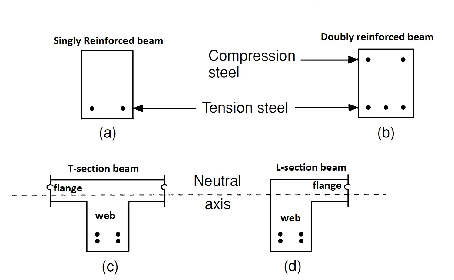
The beam design example you've just completed forms a solid foundation for understanding how to design structural elements in accordance with design code provisions. While the beam we analyzed was simply supported, it's important to note that there are various other types of beams—such as cantilever and continuous beams—as well as flanged beams like T-beams, I-beams, and L-beams, each classified by their cross-sectional shapes.
Design codes go beyond just bending and shear. They include detailed requirements for:
- Minimum and maximum reinforcement areas
- Bar spacing and placement
- Curtailment (cutting off) of bars
- Proper anchorage and development lengths
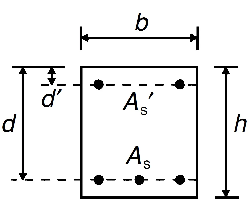
So while our example focused on the fundamentals, a real construction project (which we’ll soon be tackling) would also require considerations like minimum compression reinforcement and other essential provisions.
The goal of these simplified examples—starting with the beam and now moving to a slab—is to equip you with core design skills that will enhance your understanding and control of structural analysis software. Without this foundation, you risk blindly accepting software outputs that may be incorrect or misleading.
From Manual to Software – Understanding ProtaStructure
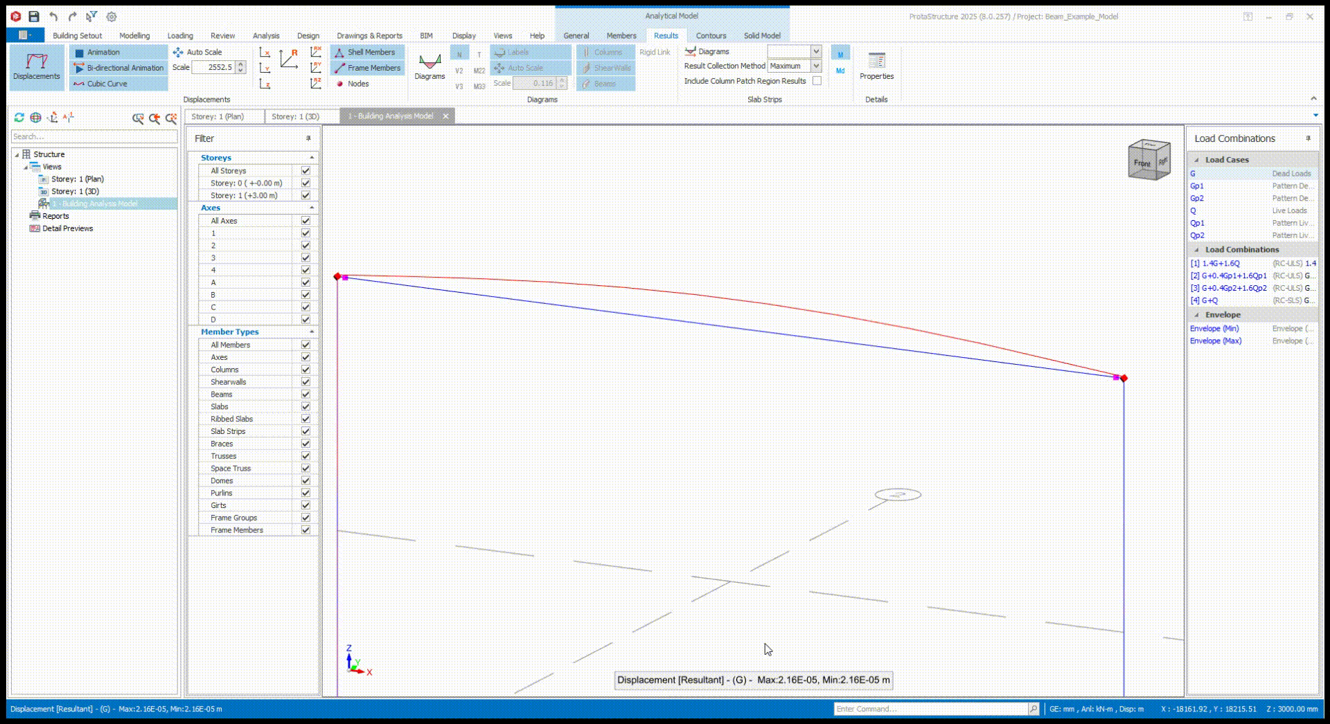
In this course, we’ll be using ProtaStructure 2025, one of the most powerful tools in the structural engineering world. It streamlines the design process and makes structural modeling and analysis feel effortless.
To appreciate the software's capabilities, we modeled our beam example in ProtaStructure. You can swipe through the images below to view the results, including:
- The bending moment diagram
- The shear force diagram
- A visual deflection animation
- Required reinforcement
- A full analysis report generated by the software
Important Note:
ProtaStructure calculated the dead load using the beam’s clear span, which is why its output gave a maximum design shear, V of 48.1 kN, slightly different from our manual calculation of 48.4 kN.


Let's Move to Our Next Example – A Slab Model
Example 2
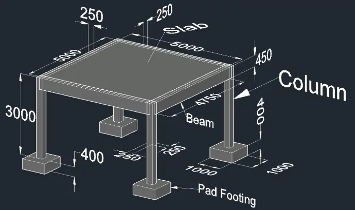
Our second example focuses on a simple reinforced concrete slab supported on all four sides by beams and resting on four corner columns. These columns transfer the loads down to the pad footings. Here are the model details:
- Slab size: 5m × 5m, depth: 250mm
- Imposed load on slab: 4 kN/m²
- Beams (4): Clear span 4.75m, size 250mm (width) × 450mm (depth)
- Columns (4): Size 250mm × 250mm, height 3m
- Soil bearing capacity: 200 kN/m²
- Characteristic strength of reinforcement, f_y = 500N/mm²
- Characteristic strength of concrete, f_cu = 25N/mm²
You can view the model setup in the image below. In this example, we'll once again use manual hand calculations to perform the structural design, and then compare our results side-by-side with those produced by ProtaStructure.
By doing this, you’ll not only deepen your understanding of code-compliant design principles but also learn how to critically assess software outputs. Using structural design software without this technical mastery can lead to serious design errors—errors that you might unknowingly pass on to clients.
After designing each structural element in the model above (slab, beams, columns, and pad footings), we’ll move on to our first real-life project: a 2-storey, flat-roof residential house recently delivered to a client. The project is shown in the image below.
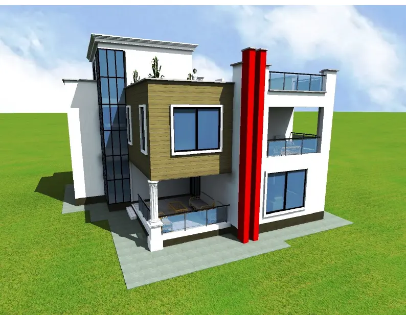
You will be provided with the architectural plans for this building and guided through a step-by-step process of delivering the structural design using ProtaStructure.
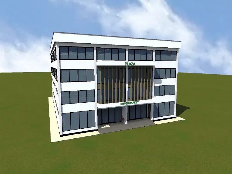
Following that, we’ll advance to our second project: a four-storey commercial building with a supermarket on the ground floor—another real-world project recently handed over to a client. An image of this project is also shown below.
Be sure to follow this full training course to the end to take full advantage of the learning experience. We are constantly adding more real-world projects to this website. To stay updated, hit the New Projects tab of this website menu so you can receive new project packages (including architectural plans, structural designs, and detailed reports) directly in your inbox as soon as they are uploaded. If you ever get stuck or need extra help, don’t hesitate to request a 1-on-1 live coaching session — we’re here to support your learning journey.
With our roadmap clearly laid out, let’s return to the second example—the slab model.
But before we proceed, take a moment to download and install ProtaStructure 2025 on your computer. Click the Download button below to get the software for free. On the download page, you’ll find an instructional video on how to install the software, along with short video modules to help you quickly get familiar with its interface and features.
Download ProtaStructure 2025 (FREE)
Once you’ve installed ProtaStructure, we’re ready for some hands-on learning. We’ve already modeled the slab example in the software, as shown in the image below. This model includes pre-filled material properties, loads, and the selected design code for your convenience.
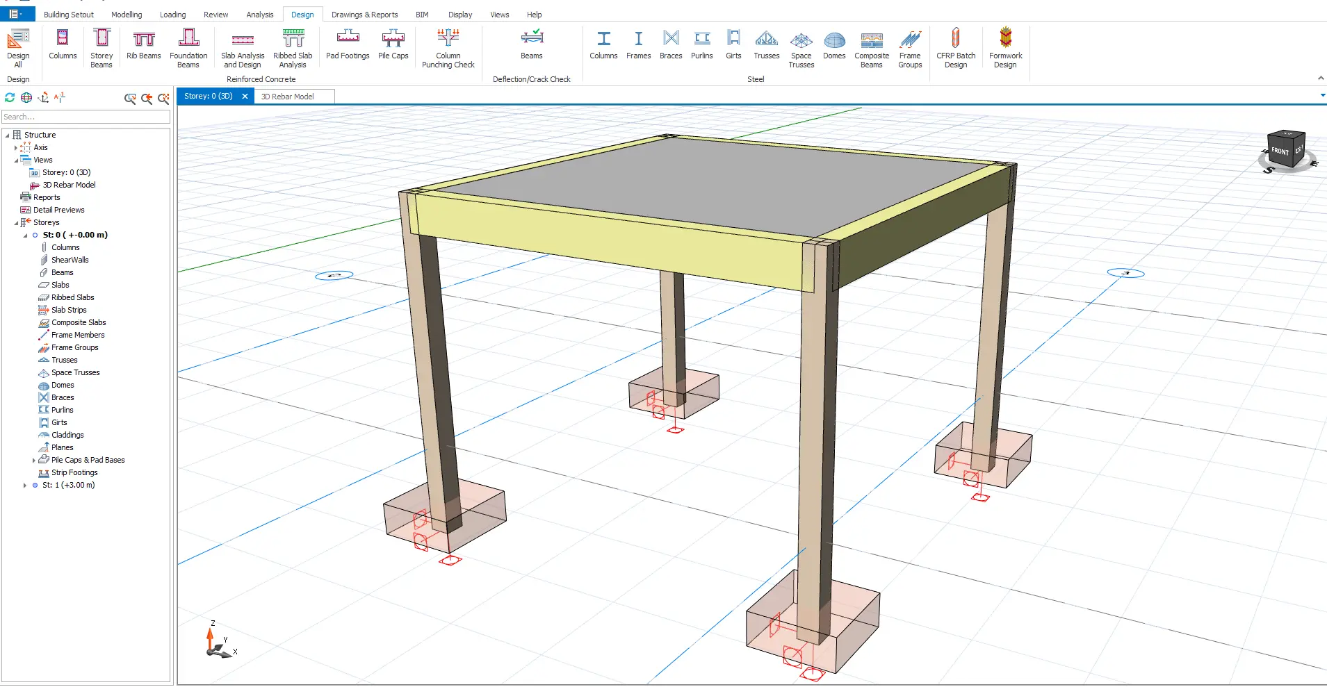
Click the link below to download the model file for just $1, and load it into your ProtaStructure environment. In this part of our training course, we’ll perform manual design calculations and compare them side-by-side with the software’s output.
Fasten your seatbelt—you're about to take a practical deep dive into structural design.
Click the “Next Page” button below to continue with the full course on Structural Design using ProtaStructure 2025. When prompted for a password, enter the one provided after checkout when you hit the Download Model button above.